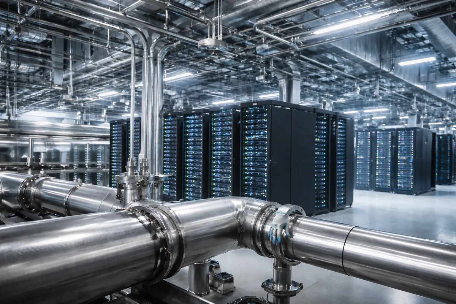
Data Center Liquid Cooling Pipe Welding is becoming increasingly important as AI servers and high-density computing drive higher cooling demands. Explore more opportunities and insight to iterate the most advanced productivities into your projects!
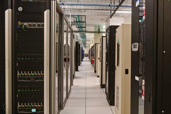
Five Weld-Quality Checkpoints for Liquid Cooling Piping
Most liquid cooling loops run through thin-wall 316L stainless tube, commonly somewhere in the 3 mm to 219 mm outer-diameter range with wall thickness from about 0.6 mm to 3 mm. That combination of the thin wall, corrosion-sensitive alloy, closed-loop fluid that never gets replaced, makes five checkpoints worth verifying on every joint, whether the work is done by hand or by machine.
- Fit-up and alignment. Thin-wall tube has very little tolerance for error. Misalignment beyond roughly 10% of wall thickness, or a root gap outside the tight range typical for this application, sets a weld up to fight bad geometry before the arc ever starts.
- Purge gas control. Because these lines run stainless against a closed, continuously circulating fluid, internal oxidation isn't cosmetic, it's a corrosion and contamination risk. Good practice means purging the pipe interior down to a low residual oxygen level before striking an arc, then holding both external and internal shielding gas through the weld and the cooldown.
- Heat input across wall thickness. A single set of parameters doesn't work across a job that mixes 0.8 mm branch tube with 2–3 mm mains. Too much heat on the thin sections causes burn-through; too little on the heavier sections leaves the root unfused.
- Internal bead profile and surface finish. Weld reinforcement, internal beading, and surface roughness all affect flow. Liquid cooling piping generally calls for full penetration with a smooth internal profile — no internal weld beads or concavity that could create a flow-restricting step or a debris trap.
- Data traceability. Large data center projects increasingly won't accept a weld log that says a joint "looked fine" to the welder. Every joint benefits from a recorded set of parameters, current, voltage, travel speed, shielding gas flow, tied to a pipe ID, diameter, and wall thickness, backed by whatever mix of visual, dye-penetrant, pressure or helium-leak, and borescope inspection the spec calls for.
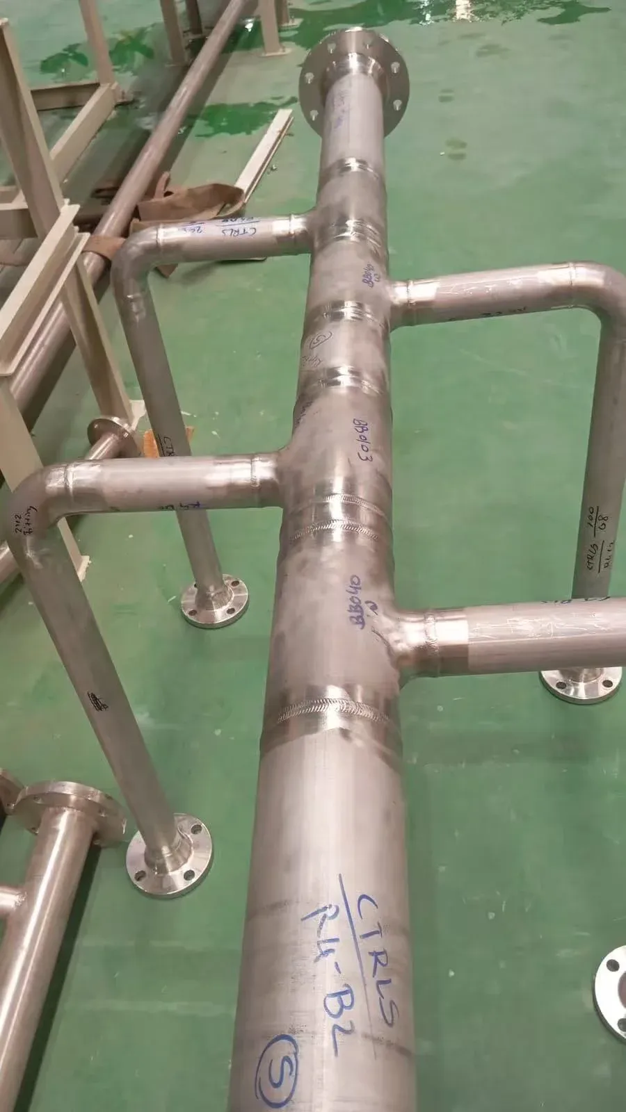
None of these checkpoints are exotic. What's changed is the volume. A single mechanical contractor might weld a few hundred stainless joints on a typical commercial job. A hyperscale liquid cooling rollout can mean tens of thousands of joints across a schedule measured in months, exactly the condition where consistency stops being a nice-to-have and becomes the whole ballgame.
Automated, Manual, or Something In Between?
The classic framework for choosing a welding process is simple: high-volume work with repeating, predictable geometry favors automation, because the process holds the same parameters pass after pass without drifting on hour six of a shift. Custom geometry, field-fit conditions, and one-off components are manual welding's territory, because no program can anticipate every field condition before a welder gets eyes on the joint.
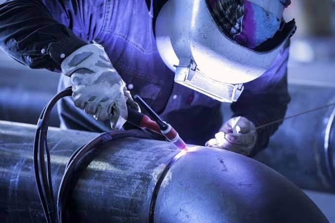
Data center liquid cooling piping doesn't sit cleanly on either side of that line. The joint count and repeating circumferential geometry point straight at automation, these are butt welds on round pipe, over and over, close to the ideal case for a programmable weld schedule. But the work also happens in mixed conditions: rack rows with limited clearance, retrofit projects where the pipe is already hung, tie-ins at odd positions, and diameter changes from a small branch line to a much larger main within the same building. A shop-bound welding station or rotator can't get into most of those spots, and pure manual TIG can't hold the joint-to-joint consistency that thousands of welds and a strict acceptance spec demand.
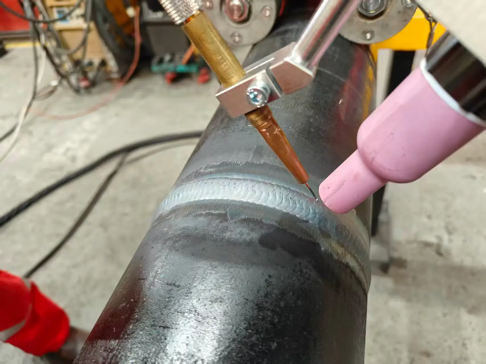
That gap is always high-volume, repeating geometry that still has to be welded in place, in whatever position the pipe happens to be in, is exactly what all-position orbital welding equipment was built to close.
All-Position Orbital Welding: Closing the Gap
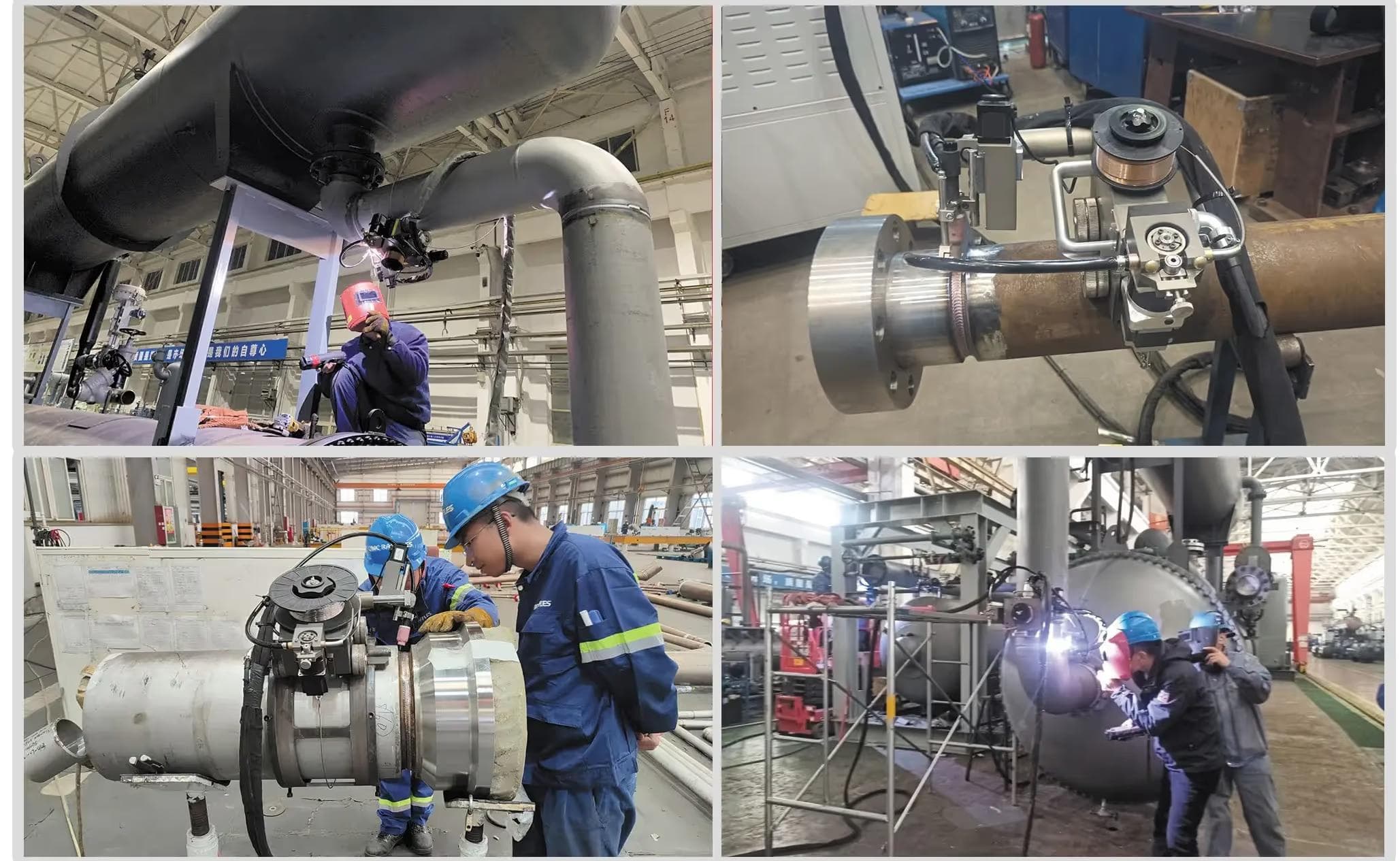
Orbital welding automates the one variable that's hardest for even a skilled welder to hold constant across a long production run: uniform torch travel, arc length, and heat input around the full circumference of a pipe joint, from the 1G rolled position through 6G fixed-position, uphill work. Jin Luding's Orbital & All-Position Welders are built specifically for that job on facility and cross-country piping — machine-driven welding from root pass through cap, without needing to rotate or reposition the workpiece itself.
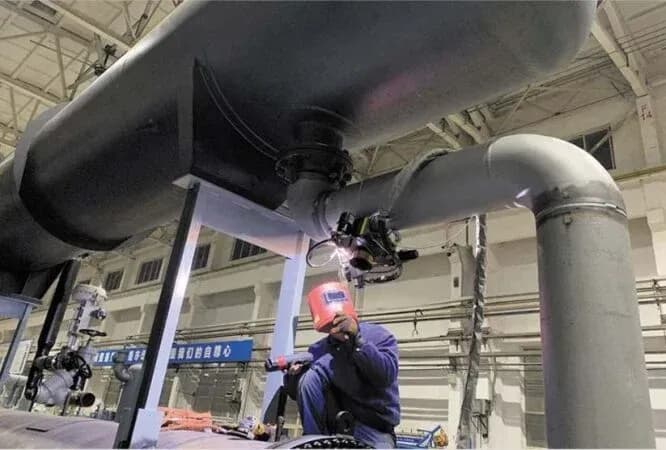
The practical advantage for liquid cooling installs is setup speed and portability. Instead of a rotator or positioner, the welding head clamps directly onto the pipe's own outer surface with a magnetic-wheel drive and orbits the joint under programmed control. A crew can set up and weld a joint on pipe that's already racked, hung, or routed through a tight equipment row, which describes most of a data center's secondary and tertiary cooling distribution network, without the fixturing overhead a shop-style orbital system would need.
Two features carry straight over to the weld-quality checkpoints above:
- Programmable procedure memory. Both machines store up to 30 complete welding procedures, recallable by number. A crew running mixed pipe sizes on a single project can dial in heat input for thin branch tube and heavier main line separately, then switch between them by selecting a stored program instead of hand-adjusting parameters joint to joint.
- Multi-angle torch and oscillator control. Radial, axial, and angular torch adjustment, combined with a programmable oscillator for bead width and dwell time, gives the operator the same fine control over penetration and bead profile the checkpoints above call for — without depending on one welder's hand staying steady at hour eight of a shift.
Matching the Machine to the Joint: MIG vs. Hot Wire TIG
Luding's orbital pipeline solution ships as two compatible platforms, and the choice between them comes down to the joint, the material, and how much post-weld finish work the spec allows.
APF-MIG All-Position Auto Welding Machine is a magnetic-wheel orbital MIG system built for carbon and alloy steel pipe-to-pipe circumferential seams, DN90 and up. It's the higher-deposition option: faster travel, well suited to larger-diameter mains and the structural steel piping racks that run alongside a data center's liquid cooling network, with 8-section parameter programming for tuning penetration at different points around the joint.
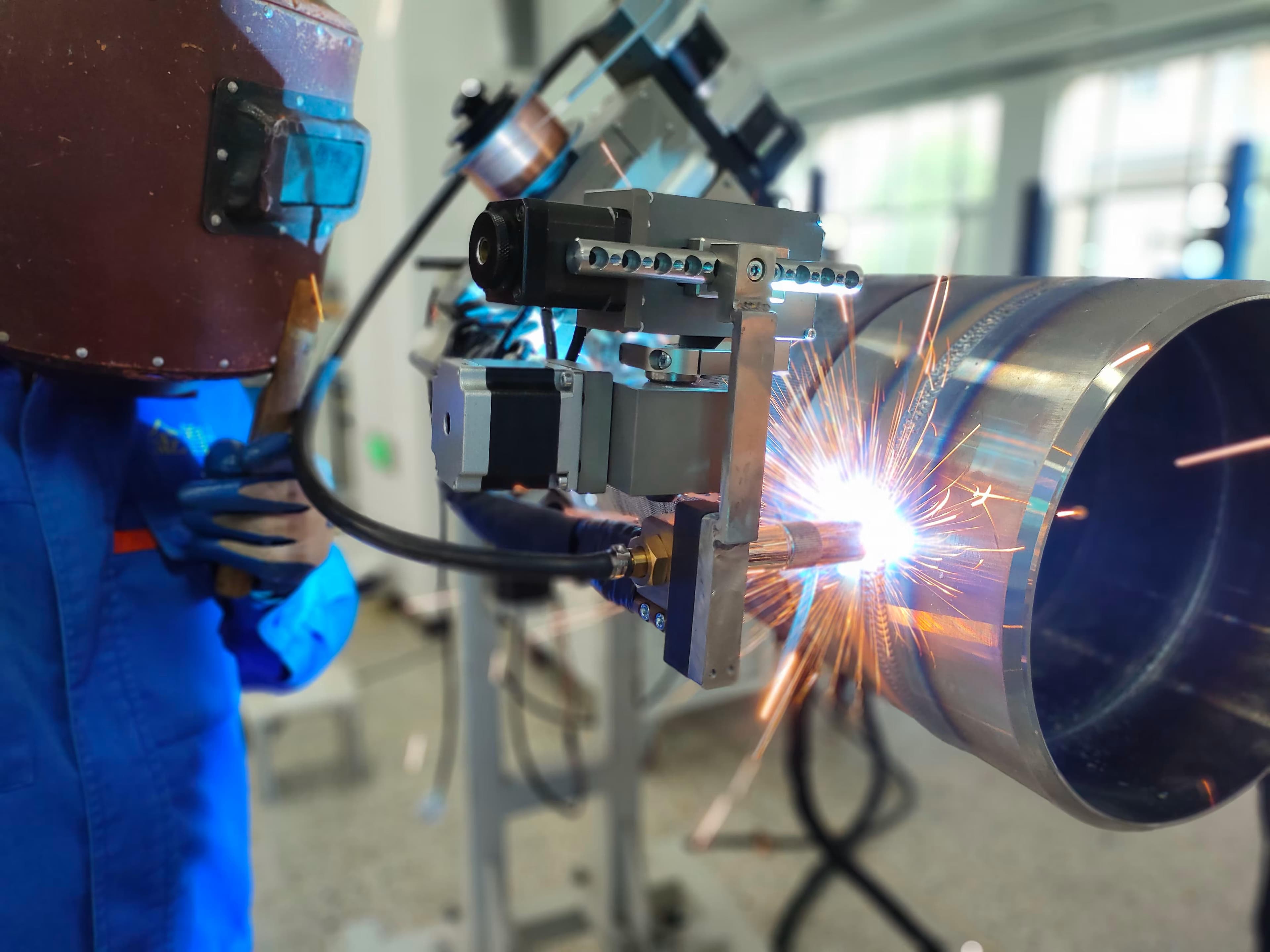
APF-RST All-Position Hot Wire TIG Welding Machine is the better fit for the corrosion-sensitive, thin-wall 316L stainless tube that makes up most of an actual coolant loop. Hot wire TIG gives tighter heat control and a cleaner internal bead than MIG on thin sections, which matters directly for the internal-oxidation and flow-restriction checkpoints covered earlier. It carries the same magnetic-wheel drive, 30-procedure memory, and touchscreen control as the MIG version, plus an integrated arc voltage controller and forced-circulation water cooling for continuous duty.
Both machines start at DN90 and scale up from there, down to roughly 89 mm with orbital tracking on the smaller end, and both accept optional non-magnetic rail kits for welding stainless and other non-ferrous material where the standard magnetic-wheel drive has nothing to grip.
FAQ: Orbital Welding for Data Center Cooling Loops
Can orbital welding handle 316L stainless steel liquid cooling pipe? Yes. The standard magnetic-wheel drive is built for magnetic materials like carbon and alloy steel; for non-magnetic 316L stainless, both the APF-MIG and APF-RST accept an optional special track that lets the same platform weld stainless coolant tube.
What pipe diameter range does all-position orbital welding cover? Both machines are rated from DN90 and up, with the APF160 series covering roughly 159 mm and larger and the APF100 series roughly 133 mm and larger — plus orbital tracking capability down to around 89 mm — which spans most branch, distribution, and main piping used in liquid cooling loops.
Is hot wire TIG or MIG better for data center coolant piping? Hot wire TIG generally gives a cleaner, more controllable internal bead on thin-wall stainless tube, which is the more common material in an actual coolant loop. MIG is the faster option for higher-deposition welding on carbon and alloy steel structural or utility piping running through the same project.
Does orbital welding meet data center documentation and traceability requirements? The programmable, procedure-memory-based control on both machines makes it straightforward to log welding parameters — current, travel speed, oscillator settings — against a stored procedure number for each joint, supporting the kind of weld traceability large data center projects increasingly require at close-out.
How much setup time does orbital welding save over manual TIG on site? The biggest saving is in fixturing, not just weld time. Because the magnetic-wheel head clamps directly onto the pipe's outer surface, crews don't need to rotate or reposition the workpiece to weld it — a step that both manual welding and shop-style rotator setups require.
Get a Machine Configuration for Your Project
Every liquid cooling project mixes pipe sizes, materials, and site conditions differently, and the right orbital welding setup depends on the specifics of the job — branch tube diameters, wall-thickness range, how much of the run is carbon steel versus stainless, and how tight site access actually is.
Request a quote from Luding's engineering team, or go straight to the Orbital & All-Position Welders solution page to compare the APF-MIG and APF-RST specifications side by side.